
Why?
Many of us grew up during the boom phase of computer development when creativity and community development thrived. Before the giants like Intel, AMD, and nVidia held all development of new technology, it was common place to see small startups building their own computers. Many companies started in a garage and grew to be well known conglomerates, but this article isn't about them; its about the creativity and passion of every-day people building technology.
Some of us perhaps even wondered how these computer components worked to deliver our user experience. And in today's entry, we will go over the basics needed to build a video card. We will build the simplest card possible to understand what is required.
Components of a video card
There are only three types of signals we need to generate to deliver video to a VGA monitor:
- VSYNC - vertical sync signal that happens every time the screen has fully been rendered
- HSYNC - horizontal sync signal that happens every time one line has been drawn
- RGB - Red, Green, and Blue analog signal between 0 and 0.7 volts.
That's it!
Timing of a monitor
From the old days of ray tubes and CRT monitors, digital monitors adopted the same approach and timing sequences to rendering a frame on the screen.
A "ray" starts from the top left of your monitor, and for each clock cycle, moves one pixel across. The data on the Red, Green, and Blue color lines will determine the color of that pixel.
Each row of pixels has a visible area - that is rendered to the screen, and an invisible area - traditionally used to point the ray tube to the next line and other side. After all rows are processed, another invisible area exists to move the ray to the top of the screen.
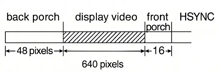
Various standards exist for different resolutions and refresh rates. One of the most common is 640 x 480 @ 60 Hz. Let's look at how timing works for this resolution.
There is a 48 pixel clock period called the back porch. Video is not displayed during this period. Then there is a 640 pixel clock period used to display the 640 pixels across your screen, followed by a 16 pixel period front porch, and a 96 pixel clock period called the HSYNC. This is one of our signals that we need to generate for the monitor.
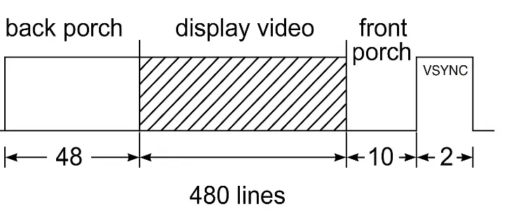
Vertically there is a similar mechanism with 33 line's worth of back porch, followed by 480 lines of video, then 10 lines of front porch and finally 2 lines of a VSYNC signal - this is the other signal we provide to the monitor.
The monitor will detect the resolution and frequency of our signal and configure itself to display at that resolution based on how often we send these HSYNC and VSYNC signals and duration of each..
Data
Great, so far we have everything we need (HSYNC and VSYNC signals) to have our monitor recognize a valid signal output and turn on to 640x480 resolution at 60Hz. Now we want to display something to the screen.
We need memory that will have our pixel data stored and ready to draw. To keep things simple yet colorful, we can use a 256 color palette for our video card. This gives us 8 bits, or 1 byte per pixel - an easy to work with standard.
Each byte in our memory will represent the color of a pixel on the screen, and we will arrange our data by using the x and y coordinates on the screen as the address of the pixel data in memory.
Counters
To generate these signals, we need to have some way to count clock cycles, and set or clear a bit for each sync signal.
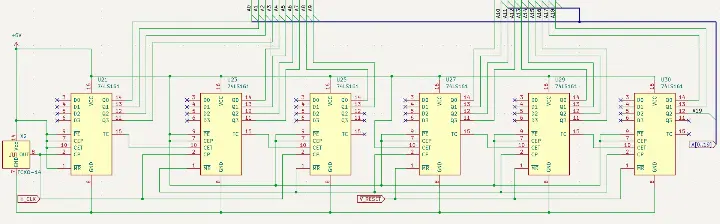
To facilitate counting, we will have a clock input of 25.25Mhz, as prescribed by the specifications. We will connect 74HC161 binary counters together to form counters with enough bits for each of our vertices.
For horizontal counters, we need to count to 800 - that will require 10 bits. For vertical we will need to count to 525 - requiring 10 bits.
Since we are building a prototype and want to keep things simple, we will skip every other count for horizontal and vertical counters, effectively giving us a 320x240 resolution. This can be done with 9 bits for horizontal and 9 bits for vertical.
This is what our counter circuit looks like in KiCad
Shared Memory
To keep things simple, our MCU or external CPU can write directly to the video memory. This memory is used by the video card to display pixel data on the screen.
We have to be careful with timing though. Remember those aforementioned periods when we are not displaying anything on the screen? That is going to be our time to write new data to memory.
Putting it together
Let's look at what we have defined so far at a high level
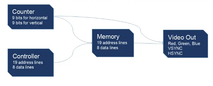
We have a counter that generates our clock for displaying pixels on the screen, as well as generating the HSYNC and VSYNC signals for the monitor.
We have a controller and the counter sharing access to memory, taking turns displaying and updating the contents of the memory.
And we have the memory drawing pixels out to the RGB lines.
Designing the electrical components
Let's list out everything we need:
- Clock
- Horizontal Counter
- Vertical Counter
- Combinational Logic Circuit - to determine when to generate the HSYNC and VSYNC signals, as well as inform the controller if the memory is being used to draw or not.
- Memory with at least 2^18 bytes of memory space to accommodate our 9x9 address space.
- Controller - Computer or MCU to update contents of video memory
- DAC - Digital to Analog converter
For a clock, we will use a quartz crystal oscillator.
As previously mentioned we will rely on 74HC161 ICs to generate our counters.
For combinational logic, we will rely on using a PLD; we can keep our component count down and change timing and other constraints without having to change any hardware/reprint the PCB.
Memory - we will use a Samsung K6X8008C2B-TF55 SRAM module with 1MB of storage. It has 19 address lines; we will use 18 for our pixel location, and we have 1/2 of the memory space to use for anything else we'd like.
Controller - we need something with 19 pins for address and 8 pins for data, as well as 5 or 6 additional control pins. A good choice for cheap and effective MCU would be an arudino duo. They are readily available and priced below $10.
DAC - we will use a resistor network for 3 bits of red data, 3 bits of green data, and 2 bits of blue data.
Circuit
Click here to see a detailed circuit
You can download all artifacts for the KiCad project on github:
https://github.com/levvayner/VGA_PLD/tree/main/VGA_SRAM_Shield
What's next?
Next we will set up a video card framework for our chosen controller, arduino duo. We will first create a way to work with the memory, then create functionality on top to execute typical video card related functions. Things like Draw Pixel, Draw Line, Draw Triangle, Draw Text, as so on.